The same plot in 14 other libraries — JavaScript: Chart.js, D3.js, Apache ECharts, Highcharts; Python: Altair, Bokeh, lets-plot, Matplotlib, Plotly, plotnine, Pygal, Seaborn; R: ggplot2; Julia: Makie.jl. Compare all 15 side by side: Polar Line Plot in Python, R, Julia and JavaScript.
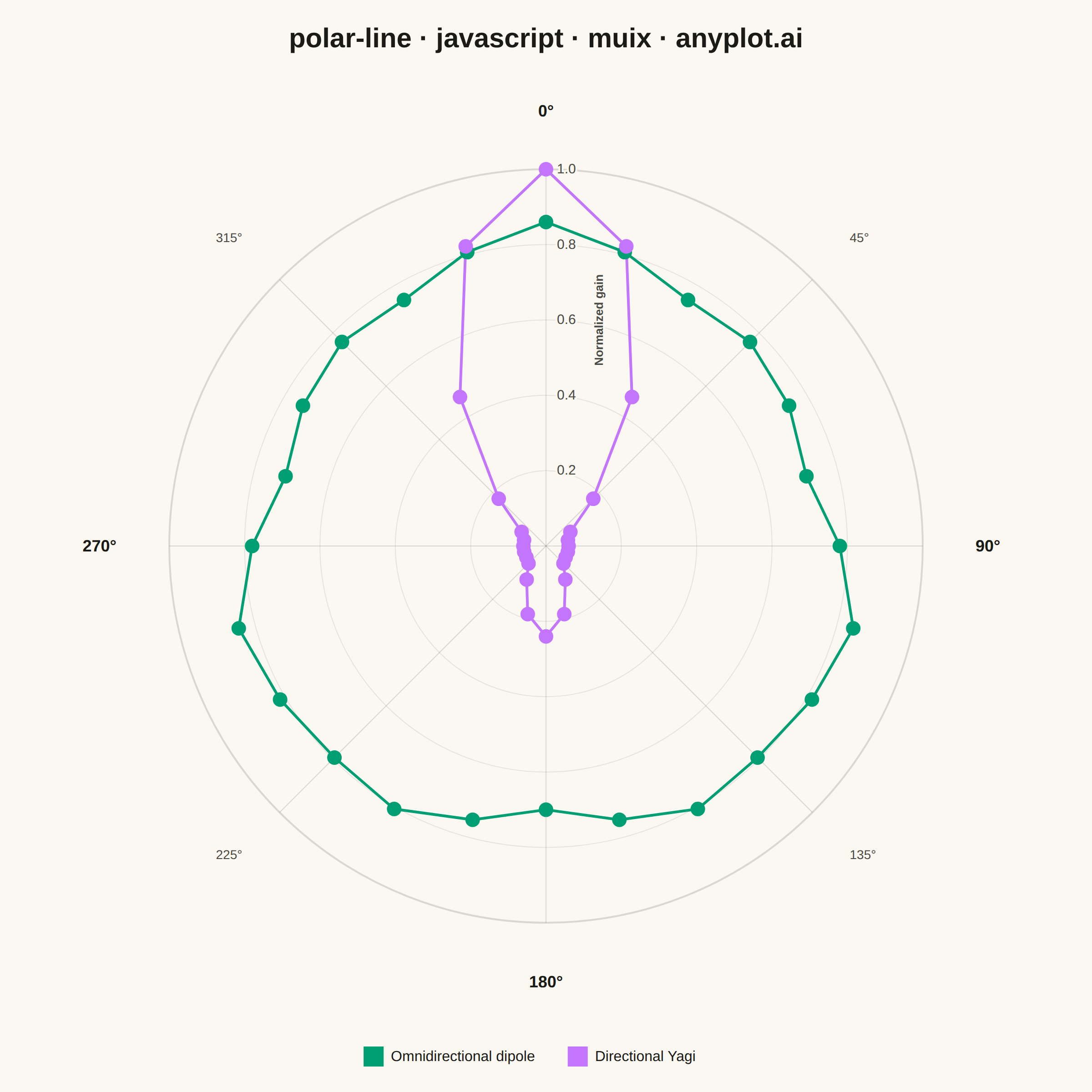
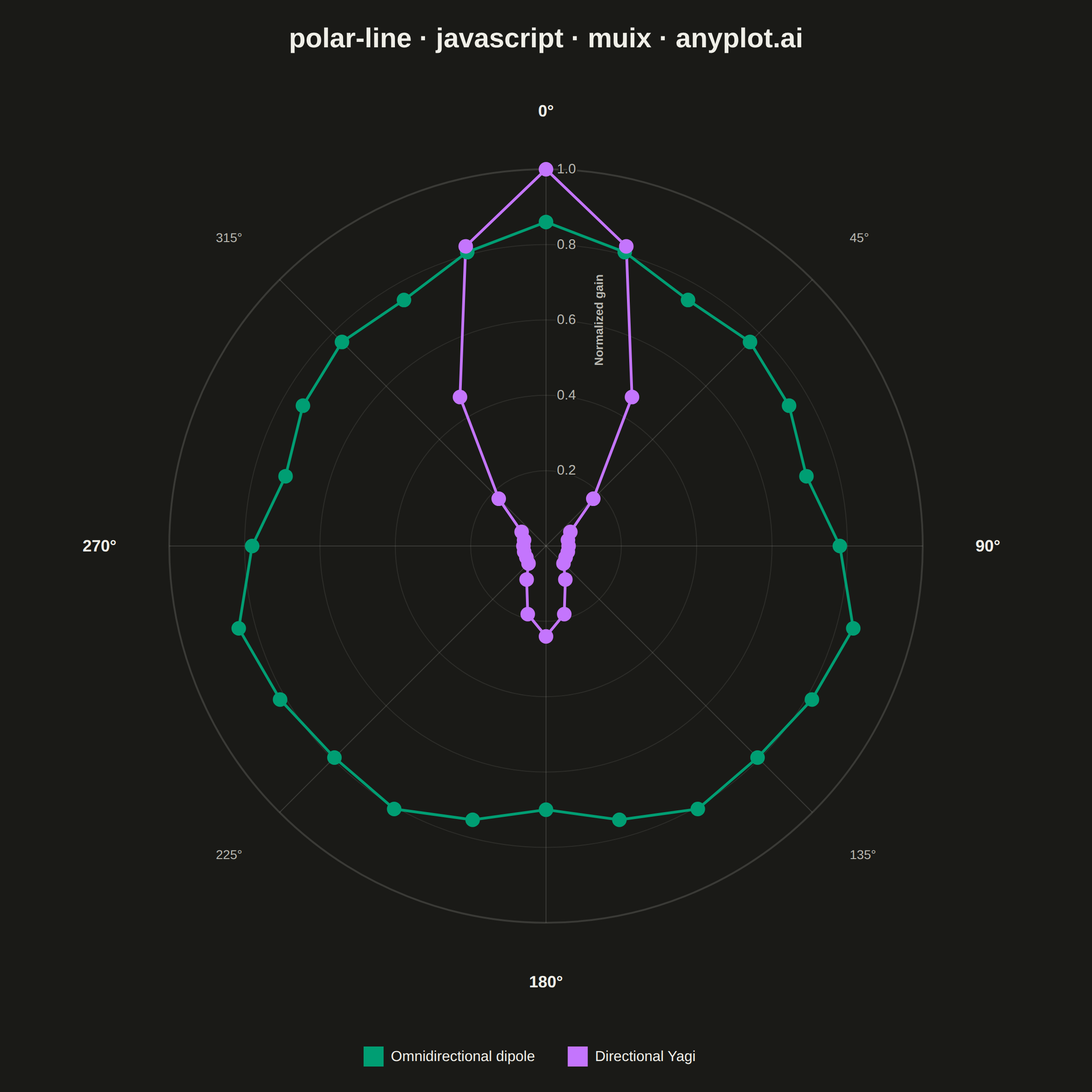
A line plot rendered in polar coordinates, where data points are connected with lines around a circular axis. The angle (theta) typically represents a cyclical variable while the radius shows magnitude.
// anyplot.ai
// polar-line: Polar Line Plot
// Library: muix 7.29.1 | JavaScript 22.23.2
// Quality: 87/100 | Created: 2026-09-05
//# anyplot-orientation: square
// anyplot.ai
// polar-line: Polar Line Plot
// Library: MUI X Charts | React | Node 22
// License: @mui/x-charts — MIT (community). Pro/Premium are out of scope.
// Quality: pending | Created: 2026-09-05
import { ChartContainer } from "@mui/x-charts/ChartContainer";
import { ScatterPlot } from "@mui/x-charts/ScatterChart";
import { ChartsLegend } from "@mui/x-charts/ChartsLegend";
import { ChartsTooltip } from "@mui/x-charts/ChartsTooltip";
import { useDrawingArea } from "@mui/x-charts/hooks";

// @mui/x-charts 7.x community has no polar/radial-line chart component (a
// PolarProvider exists internally but isn't part of the public export
// surface), so the plot is composed on MUI X's own charting surface:
// ChartContainer sizes the <svg> + theme, and useDrawingArea() gives the plot
// rect the hand-drawn ring/spoke/polyline geometry is mapped onto — real
// trigonometry from the real gain values, not faked chrome. Each series'
// angle/gain pairs are ALSO registered as a genuine `scatter` series (mapped
// through a matching linear xAxis/yAxis so the pixels line up exactly with
// the hand-drawn polylines), so ChartsLegend and ChartsTooltip read real
// series data and MUI's own hover-highlight works — nothing here is faked.

const t = window.ANYPLOT_TOKENS;
const size = window.ANYPLOT_SIZE;

// Theme-adaptive chrome (ThemeProvider handles MUI text; these are for our SVG).
const INK = t.ink;
const INK_SOFT = t.inkSoft;
const GRID = t.grid;
const PAGE_BG = t.pageBg;
const OMNI_COLOR = t.palette[0]; // Imprint palette position 1 — always first series
const YAGI_COLOR = t.palette[1];

// --- Data (in-memory, deterministic): simulated far-field radiation patterns
// for two antenna types, sampled every 15° of azimuth — the classic "line
// plot in polar coordinates" use case from RF/antenna engineering ------------
const ANGLE_STEP = 15;
const ANGLES = Array.from({ length: 360 / ANGLE_STEP }, (_, i) => i * ANGLE_STEP);
const GAIN_MAX = 1; // normalized gain, 0-1
const RINGS = [0.2, 0.4, 0.6, 0.8, 1.0];
const DEGREE_TICKS = [0, 45, 90, 135, 180, 225, 270, 315];

// Omnidirectional dipole: near-circular with the small real-world ripple that
// distinguishes an actual antenna from an idealized isotropic radiator.
const omniGain = (deg) => {
  const rad = (deg * Math.PI) / 180;
  return 0.78 + 0.05 * Math.cos(3 * rad) + 0.03 * Math.cos(7 * rad);
};

// Directional Yagi: a narrow forward main lobe (boresight at 0°) plus a small
// back lobe — modeled with clamped cosine powers rather than measured data.
const yagiGain = (deg) => {
  const rad = (deg * Math.PI) / 180;
  const c = Math.cos(rad);
  const mainLobe = Math.pow(Math.max(0, c), 6);
  const backLobe = 0.18 * Math.pow(Math.max(0, -c), 10);
  return Math.min(1, 0.06 + 0.94 * mainLobe + backLobe);
};

const omni = ANGLES.map((deg) => ({ deg, gain: omniGain(deg) }));
const yagi = ANGLES.map((deg) => ({ deg, gain: yagiGain(deg) }));

// 0° points to the top (boresight), gain grows clockwise with azimuth — same
// convention as a compass rose, matching the spoke labels drawn below.
const toRad = (deg) => ((deg - 90) * Math.PI) / 180;

// --- Real MUI X scatter series for the sampled points ------------------------
// A shared linear xAxis/yAxis pair whose domain is sized so that gain 1
// (GAIN_MAX) lands exactly `DATA_R` px from centre — the same radius the
// hand-drawn rings/polylines below use — so the real MUI scatter dots
// register precisely on top of the custom SVG geometry. The yAxis grows
// upward in data space while SVG grows downward in pixel space, so the y
// component is negated here to compensate.
const MARGIN = 110;
const HALF = Math.min(size.width, size.height) / 2 - MARGIN;
const DATA_R = HALF - 76;
const DOMAIN = HALF / DATA_R;
const toPoint = (deg, gain) => {
  const a = toRad(deg);
  const frac = gain / GAIN_MAX;
  return { x: frac * Math.cos(a), y: -frac * Math.sin(a) };
};
const SERIES = [
  {
    type: "scatter",
    data: omni.map(({ deg, gain }) => ({ ...toPoint(deg, gain), id: `omni-${deg}`, deg, gain })),
    color: OMNI_COLOR,
    markerSize: 8,
    label: "Omnidirectional dipole",
    valueFormatter: (v) => `${v.deg}° · gain ${v.gain.toFixed(2)}`,
  },
  {
    type: "scatter",
    data: yagi.map(({ deg, gain }) => ({ ...toPoint(deg, gain), id: `yagi-${deg}`, deg, gain })),
    color: YAGI_COLOR,
    markerSize: 8,
    label: "Directional Yagi",
    valueFormatter: (v) => `${v.deg}° · gain ${v.gain.toFixed(2)}`,
  },
];

// --- Polar layer: rendered as children inside MUI X's ChartsSurface ----------
function PolarLayer() {
  const area = useDrawingArea();
  const cx = area.left + area.width / 2;
  const cy = area.top + area.height / 2;
  const half = Math.min(area.width, area.height) / 2;
  const R = half - 76; // data radius; the margin to `half` holds degree labels
  const labelR = half - 18;

  const point = (deg, gain) => {
    const a = toRad(deg);
    const r = (gain / GAIN_MAX) * R;
    return [cx + r * Math.cos(a), cy + r * Math.sin(a)];
  };
  const polylinePoints = (series) =>
    series.map(({ deg, gain }) => point(deg, gain).join(",")).join(" ");

  return (
    <g>
      {/* Concentric gain rings — outer solid, inner lighter so the grid stays subtle */}
      {RINGS.map((level) => (
        <circle
          key={`ring-${level}`}
          cx={cx}
          cy={cy}
          r={(level / GAIN_MAX) * R}
          fill="none"
          stroke={GRID}
          strokeWidth={level === GAIN_MAX ? 2 : 1}
          strokeOpacity={level === GAIN_MAX ? 1 : 0.6}
        />
      ))}

      {/* Radial spokes at every 45° of azimuth, with degree labels */}
      {DEGREE_TICKS.map((deg) => {
        const [ox, oy] = point(deg, GAIN_MAX);
        const a = toRad(deg);
        const lx = cx + labelR * Math.cos(a);
        const ly = cy + labelR * Math.sin(a);
        const cos = Math.cos(a);
        const sin = Math.sin(a);
        const anchor = cos > 0.3 ? "start" : cos < -0.3 ? "end" : "middle";
        const baseline = sin > 0.5 ? "hanging" : sin < -0.5 ? "auto" : "central";
        const isCardinal = deg % 90 === 0;
        return (
          <g key={`spoke-${deg}`}>
            <line x1={cx} y1={cy} x2={ox} y2={oy} stroke={GRID} strokeWidth={1} />
            <text
              x={lx}
              y={ly}
              fill={isCardinal ? INK : INK_SOFT}
              fontSize={isCardinal ? 18 : 14}
              fontWeight={isCardinal ? 700 : 400}
              textAnchor={anchor}
              dominantBaseline={baseline}
            >
              {`${deg}°`}
            </text>
          </g>
        );
      })}

      {/* The two radiation-pattern lines — closed loops since azimuth wraps at 360° */}
      <polygon
        points={polylinePoints(omni)}
        fill="none"
        stroke={OMNI_COLOR}
        strokeWidth={3}
        strokeLinejoin="round"
      />
      <polygon
        points={polylinePoints(yagi)}
        fill="none"
        stroke={YAGI_COLOR}
        strokeWidth={3}
        strokeLinejoin="round"
      />

      {/* Gain (radius) tick labels, offset off the top spoke, drawn last so
          they sit above the pattern lines that cross it. A page-background
          stroke halo (instead of a flat rect) keeps them legible without the
          utilitarian pill look. */}
      {RINGS.map((level) => {
        const ty = cy - (level / GAIN_MAX) * R;
        const label = level.toFixed(1);
        return (
          <text
            key={`tick-${level}`}
            x={cx + 12}
            y={ty}
            fill={INK_SOFT}
            fontSize={15}
            textAnchor="start"
            dominantBaseline="central"
            stroke={PAGE_BG}
            strokeWidth={4}
            strokeLinejoin="round"
            paintOrder="stroke"
          >
            {label}
          </text>
        );
      })}

      {/* Descriptive label for the radial (gain) axis, running alongside the
          ring ticks so the numbers aren't bare digits */}
      <text
        x={cx + 58}
        y={cy - (RINGS[2] / GAIN_MAX) * R}
        fill={INK_SOFT}
        fontSize={13}
        fontWeight={600}
        textAnchor="middle"
        dominantBaseline="central"
        stroke={PAGE_BG}
        strokeWidth={4}
        strokeLinejoin="round"
        paintOrder="stroke"
        transform={`rotate(-90, ${cx + 58}, ${cy - (RINGS[2] / GAIN_MAX) * R})`}
      >
        Normalized gain
      </text>
    </g>
  );
}

// --- Title drawn on the surface -----------------------------------------------
function Title() {
  return (
    <text x={size.width / 2} y={52} fill={INK} fontSize={30} fontWeight={700} textAnchor="middle">
      polar-line · javascript · muix · anyplot.ai
    </text>
  );
}

// --- Chart (default-exported component — the harness mounts it) --------------
export default function Chart() {
  return (
    <ChartContainer
      width={size.width}
      height={size.height}
      series={SERIES}
      xAxis={[{ scaleType: "linear", min: -DOMAIN, max: DOMAIN }]}
      yAxis={[{ scaleType: "linear", min: -DOMAIN, max: DOMAIN }]}
      margin={{ top: MARGIN, bottom: MARGIN, left: MARGIN, right: MARGIN }}
      skipAnimation
    >
      <Title />
      <PolarLayer />
      <ScatterPlot />
      <ChartsLegend
        position={{ vertical: "bottom", horizontal: "middle" }}
        labelStyle={{ fontSize: 16 }}
        itemMarkWidth={22}
        itemMarkHeight={22}
        markGap={8}
        itemGap={36}
      />
      <ChartsTooltip trigger="item" />
    </ChartContainer>
  );
}
Runnable source as JSON, for any HTTP client: https://api.anyplot.ai/specs/polar-line/muix/code. Any spec id and library id listed in llms-full.txt fit the same URL shape; every URL below is complete and callable.
{
  "spec_id": "polar-line",
  "language": "javascript",
  "library": "muix",
  "page": "https://anyplot.ai/polar-line/javascript/muix",
  "hub": "https://anyplot.ai/polar-line",
  "code_json": "https://api.anyplot.ai/specs/polar-line/muix/code",
  "spec_json": "https://api.anyplot.ai/specs/polar-line",
  "render_light_png": "https://storage.googleapis.com/anyplot-images/plots/polar-line/javascript/muix/plot-light.png",
  "render_dark_png": "https://storage.googleapis.com/anyplot-images/plots/polar-line/javascript/muix/plot-dark.png",
  "interactive_light_html": "https://storage.googleapis.com/anyplot-images/plots/polar-line/javascript/muix/plot-light.html",
  "interactive_dark_html": "https://storage.googleapis.com/anyplot-images/plots/polar-line/javascript/muix/plot-dark.html",
  "quality_score": 87.0,
  "license": "MIT",
  "guide": "https://anyplot.ai/llms.txt"
}
Part of Polar Line Plot on anyplot.ai.